Thermofluids / Mechanical Design
—
2025
Double-Pipe Heat Exchanger
My Role
3D CAD model development, improved heat-exchanger design and 3D-printed prototype.
Project Type
University Team Thermofluids Project
University Subject
41057 Thermofluids A
Tools & Technologies
SolidWorks · SolidWorks Flow Simulation · LMTD · ε-NTU · 3D Printing
Team Context
Team project combining experimental testing, analytical modelling, CFD and mechanical design.
Overview
The team tested parallel-flow and counter-flow operation, used measured temperatures and flow rates to calculate heat duty, LMTD and overall conductance, and compared the results with effectiveness-NTU analysis.
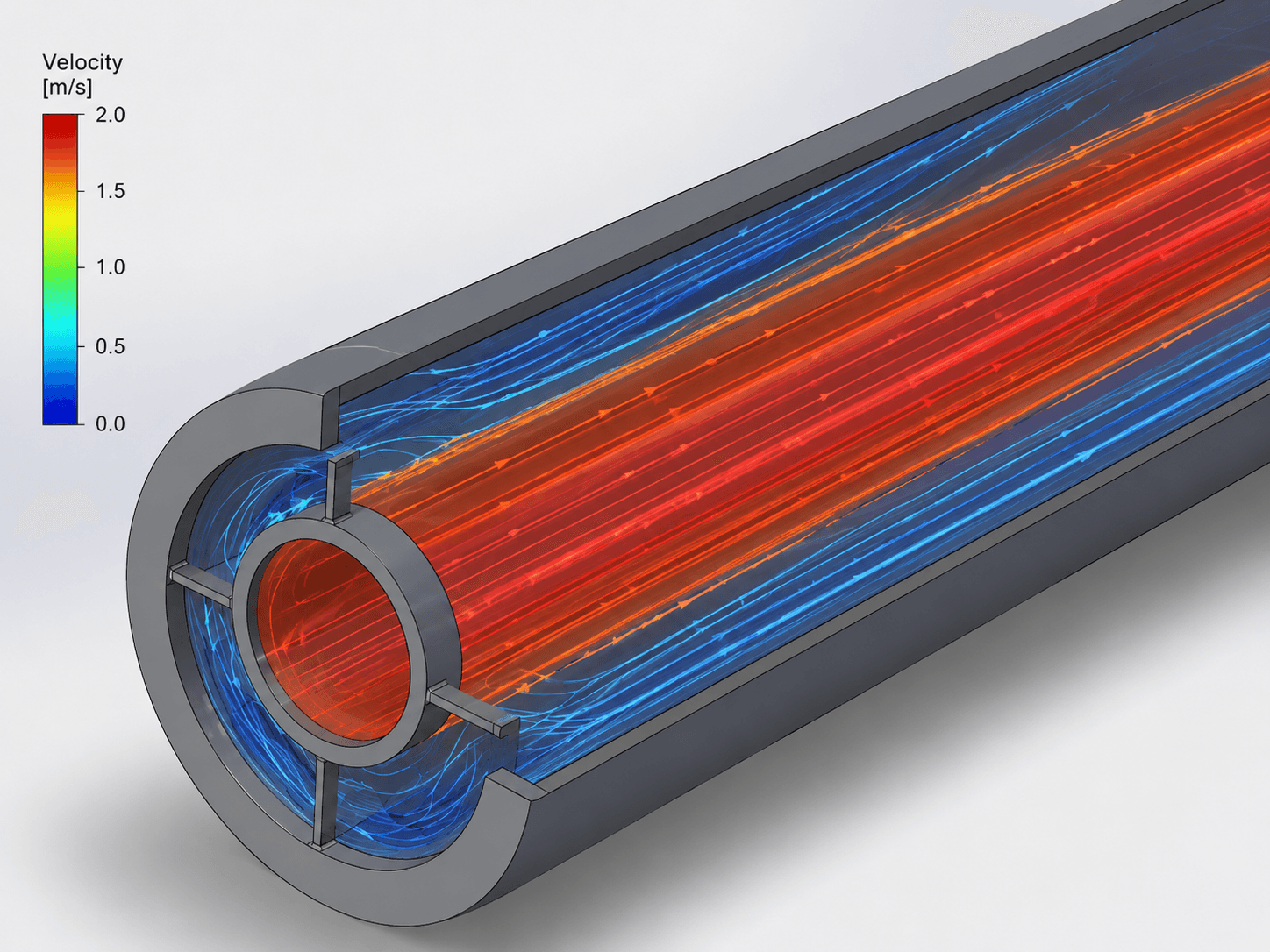
A SolidWorks Flow Simulation model was validated against the experimental system. Once the baseline model reproduced the physical behaviour closely, it became a foundation for design improvement.
My Contribution
What I owned
My documented responsibility was the three-dimensional SolidWorks model and improved physical design.
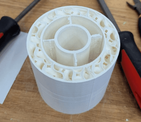
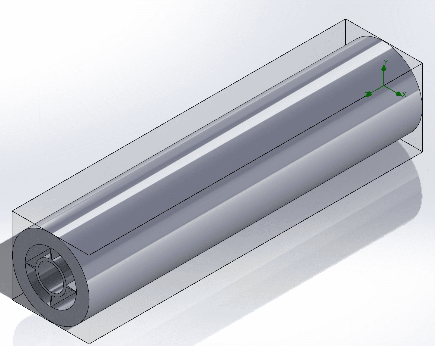
I developed the heat-exchanger geometry in CAD, including the concentric tube arrangement used by the team simulation. I then designed the improved configuration and produced a 3D-printed prototype of the longitudinal-finned double-pipe concept.
The Challenge
The numerical model had to represent the same thermal behaviour observed in the laboratory before it could be trusted for design decisions.
The project therefore had to validate the baseline against outlet temperatures and overall conductance, then improve thermal performance without an unjustified increase in flow resistance or complexity.
Constraints
Concentric double-pipe geometry.
Experimental and numerical results needed physical consistency.
Appropriate inlet conditions and material properties.
Improvements should raise effective heat transfer while keeping pressure drop reasonable.
Prototype had to be practical to CAD and manufacture.
Team responsibilities were split across experimental, analytical, CFD and design work.
System & Design Development
How the system took shape
System Architecture
Hot stream
→ inner tube
Cold stream
→ surrounding annulus
Thermal energy transfers through convection, wall conduction and convection.
Workflow:
Laboratory measurements
→ analytical LMTD / ε-NTU calculations
→ SolidWorks geometry
→ CFD model
→ experimental validation
→ improved geometry

Design Process
The project began with laboratory testing under different operating conditions and flow arrangements.
Analytical calculations quantified heat duty, logarithmic mean temperature difference and overall conductance.
I developed the 3D SolidWorks geometry and improved geometry. The team performed meshing and Flow Simulation, checked convergence and compared outlet temperatures and UA against the experiment. After validation, the model supported the design-improvement stage.
Key engineering decisions
Validate before optimising
Experimental measurements and analytical calculations were used to verify the baseline model before design optimisation.
Use longitudinal fins to increase effective area
The redesign focused on increasing available heat-transfer area while remaining compatible with the double-pipe architecture.
Make the innovation manufacturable
The improved geometry was converted into a 3D-printable prototype instead of remaining a purely numerical concept.
Testing & iteration
The baseline CFD reproduced measured outlet temperatures closely, with errors below 1% for both outlet temperatures and ~1.6% for UA.
Stable goal histories and close agreement established confidence in the numerical baseline. The improved design could then be considered against both thermal performance and flow resistance.

Final outcome
The project connected physical experimentation, analytical engineering and CAD-based numerical modelling. My contribution took the exchanger from baseline geometry into an improved, manufacturable finned design.
Results & Measurements
0.2% error in hot outlet temperature.
0.9% error in cold outlet temperature.
1.6% error in UA.
The final innovation was a longitudinal-finned double-pipe configuration that I developed as a 3D SolidWorks design and 3D-printed prototype.
Limitations
The model depends on assumptions around properties, heat loss, boundary conditions, turbulence and mesh resolution.
A 3D-printed prototype does not reproduce the thermal behaviour of a metallic exchanger. Future work should manufacture the improved geometry in a representative material and test pressure drop and thermal performance directly.
Reflection
This project strengthened the connection between CAD and thermofluids analysis for me. A geometry has to reflect the physical system and support meaningful engineering measurements.
It also demonstrated why validation matters: close experiment-CFD agreement gave the design work a stronger foundation than optimisation based on simulation alone.
Project Links