Mechanical Design / Manufacturing
—
2024
Vertical-Axis Wind Turbine

My Role
Fabricator · Testing · Report · Drafting
Project Type
University Team Mechanical Prototype
University Subject
41053 Materials and Manufacturing Engineering A
Tools & Technologies
SolidWorks · Workshop Fabrication · Wind Tunnel · PVC · Aluminium · Bearings
Team Context
Four-person team; all members contributed to fabrication, testing and reporting, with additional drafting responsibility assigned to me.
Overview
The project involved designing and fabricating a scaled vertical-axis wind turbine for simulated wind conditions.
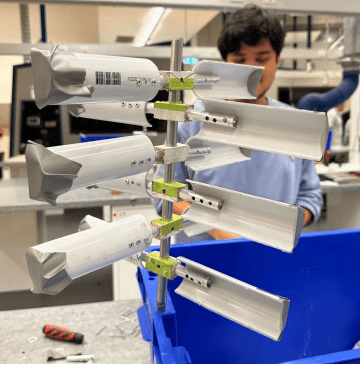
The final design used a central shaft, bearings, repeated blade modules and manually fabricated components. The prototype investigated how blade geometry, orientation and manufacturing decisions affect the ability to convert airflow into rotation.
My Contribution
What I owned
My documented role was Fabricator, Testing, Report and Drafts Person.
I participated directly in building the prototype, preparing design documentation, assembling and modifying the blades and evaluating the design in the wind tunnel.
The Challenge
The turbine needed to be light enough to respond to airflow but strong enough to hold geometry during rotation.
The first prototype would not begin rotating without a manual kick-start even under the strongest available wind setting. This indicated that blade orientation and friction losses were preventing sufficient starting torque.
Constraints
Scaled prototype using accessible lab materials.
PVC blades, aluminium shaft / connectors, wooden blocks and bearings.
Low-cost, manually fabricated components.
Listed prototype material cost ~A$7.
Manual fabrication took roughly three hours with the team.
Design needed to remain light for wind-tunnel testing.
Performance strongly affected by blade orientation and friction.
System & Design Development
How the system took shape
System Architecture
Airflow
→ curved vertical blades
→ aerodynamic drag / torque
→ central shaft rotation
→ bearing-supported output shaft
Repeated blade modules mounted around a vertical central shaft, with connector blocks transferring force into shaft rotation.
Design Process
Parts were developed in CAD, including blade geometry, side covers, connectors, mounting blocks, shaft and bearing housing.
The prototype was manually fabricated and assembled.
Initial wind-tunnel testing showed it could not self-start. The team focused on blade angle, exposed surface area and friction.
Blade orientation was adjusted, tape was added to improve structural stability and airflow interaction, and smaller friction-related modifications were made. The turbine was then retested.
Key engineering decisions
Use a vertical-axis architecture
The layout can accept wind from changing directions and remain compact, while allowing repeated blade modules to be adjusted experimentally.
Prioritise modifiable, low-cost materials
PVC, aluminium and wooden pieces were selected because they were easy to fabricate and inexpensive enough to support repeated modification.
Fix the self-start problem rather than accept kick-start operation
The team changed blade angle, added tape for stability / airflow behaviour and reduced friction until the rotor could begin turning under the same wind conditions without a kick-start.
Testing & iteration
The first tests failed because the turbine did not spin on its own.
Blade angles were adjusted, tape was applied and friction-reduction changes were made.
Repeat wind-tunnel testing showed significant improvement: the modified turbine self-started and produced more consistent, linear and smooth rotation.
Final outcome
The project delivered a functioning vertical-axis prototype and a clear design iteration supported by physical testing. The first prototype failed its basic operational goal; the final design resolved the failure through geometry and friction changes.
Results & Measurements
The final modified prototype successfully self-started in the wind tunnel. Rotation was more consistent and smooth than the first build.
Limitations
The small, low-cost prototype is not representative of commercial efficiency.
The project did not establish full electrical-generation performance. Future work should add generator integration, torque / RPM measurement and quantitative efficiency testing.
Reflection
The project showed how physical manufacturing quality can dominate performance. CAD showed ideal geometry, but the real turbine responded to blade alignment, joint stiffness, friction and assembly error.
The failure to self-start made the testing valuable because it forced the team to identify performance losses and improve the design.
Project Links