Mechanical Design / Prototyping
—
2024
Mechanical Catapult Prototype

My Role
Mechanical Design Engineer
Project Type
First-Year University Team Prototype
University Subject
48610 Introduction to Mechanical Engineering
Tools & Technologies
SolidWorks · Mechanical Design · Engineering Drawings · Workshop Fabrication · Experimental Testing
Team Context
Five-person mechanical-engineering design team.
Overview
The brief required a mechanical catapult capable of launching a standard squash ball to an adjustable target between approximately 3 and 4 metres.
The design also needed to be safe, modular, easy to transport and quick to assemble. This turned projectile motion into a complete mechanical product-development exercise.
My Contribution
What I owned
My primary responsibility was the CAD development of the catapult. I translated the selected mechanical concept into a detailed SolidWorks model, developing the geometry and arrangement of the components so the design could satisfy the project’s dimensional, assembly and functional requirements. My CAD work helped move the project from the concept-selection stage toward a manufacturable physical prototype.
The Challenge
The catapult needed sufficient energy for the full 4 metre range and fine enough adjustment to hit intermediate targets accurately.
It also had to fit inside a defined storage volume, use a rotating arm, remain stable during firing and support safe remote release.
Constraints
Squash-ball payload ~40 mm diameter and ~24 g.
Adjustable range 3–4 m.
Target diameter ~10 cm.
Mechanical components only.
One source of mechanical energy.
Rotating throwing arm.
Quick loading.
Ground-based operation.
Remote release.
Modular construction.
Frame fits provided storage container.
Arm reassembly <~5 minutes.
Operation <~3 minutes.
Prototype should remain stable during launch.
System & Design Development
How the system took shape
System Architecture
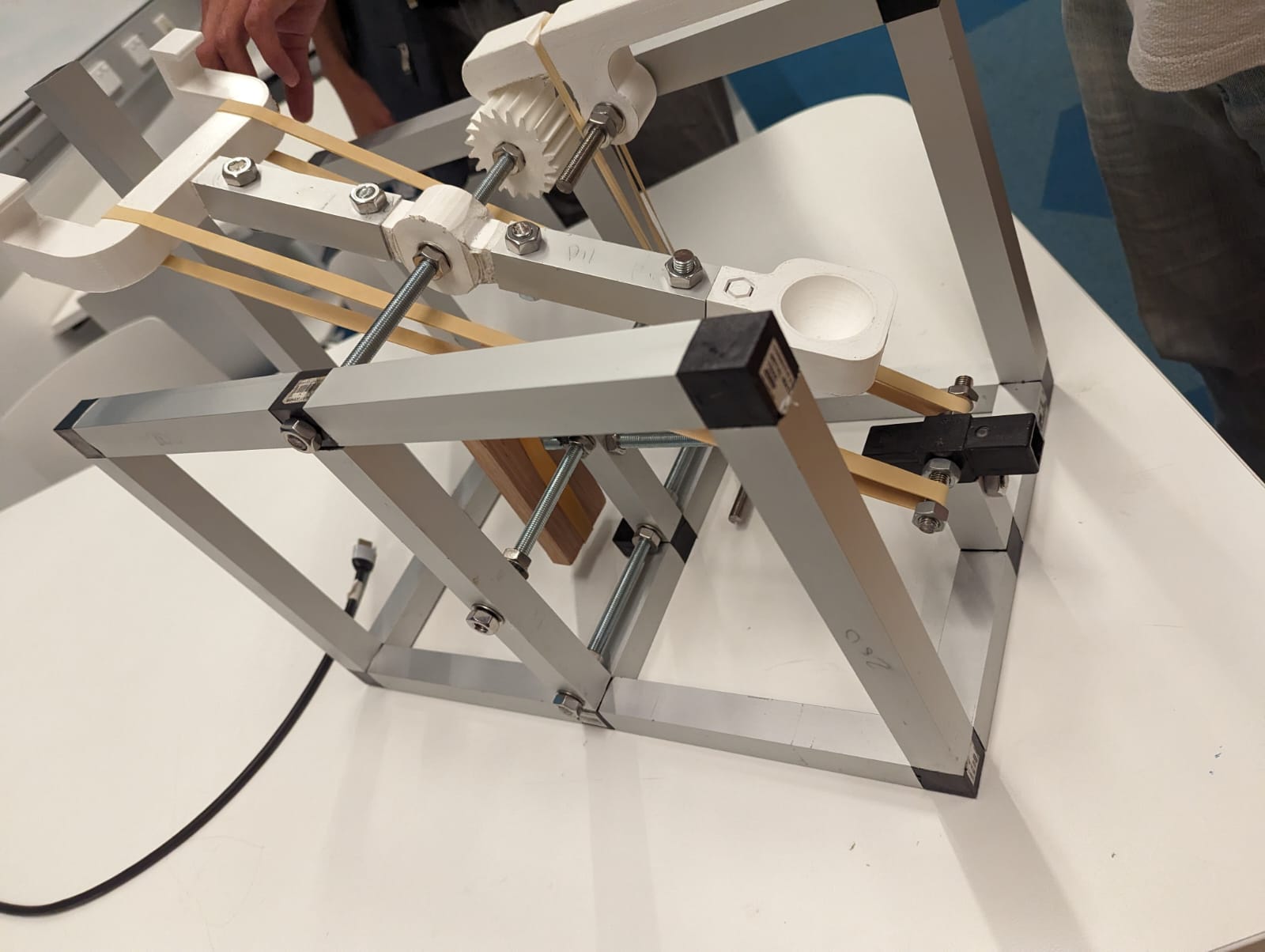
Stored elastic energy
→ rubber-band tension
Crank / notched adjustment
→ controls stored energy
Mechanical blocker / remote release
→ holds and releases system
Rotating arm
→ converts stored energy into payload velocity
Payload cup
→ launches squash ball
Rubber feet / base
→ stabilises prototype

Design Process
The brief was translated into measurable requirements.
Alternative partial solutions were generated for energy storage, distance adjustment, restraint, assembly and stability. These were combined into:
1. The Classic.
2. Spring-Shot.
3. Tiger Woods.
A weighted decision matrix compared maximum distance, adjustability, assembly, manufacturing and safety. The Classic had the strongest overall score and was selected.
The design was modelled in SolidWorks, documented through engineering drawings, manufactured and tested.
Key engineering decisions
Select the Classic using weighted criteria
The concept was chosen on adjustability, assembly, manufacturing, safety and distance rather than appearance alone.
Increase adjustment resolution
Early testing showed coarse gear positions created large gaps between achievable distances. Increasing the number of notch positions reduced the change in stored energy between settings.
Tune both launch geometry and stored energy
Gear settings alone could not remove every dead zone. The team changed launch geometry and tested two rubber bands to add another degree of adjustment.
Testing & iteration
The first 16-tooth adjustment gear produced very large changes between settings. One setting reached around 3 m, while the next could exceed ~5 m.
A 30-tooth gear reduced the spacing and produced results around 3.21–3.43 m at one setting and 3.70–3.98 m at the next.
Further refinement increased the available positions. Remaining dead zones were addressed by changing the launch setup and testing two rubber bands.
Final outcome
This was an early introduction to structured mechanical product development: requirements, concepts, CAD, drawings, fabrication and measured iteration.
Results & Measurements
The final prototype met the core objective of launching the squash-ball payload in the adjustable 3–4 metre range.
The project also produced CAD, detailed drawings, concept-selection evidence and experimental testing.
Limitations
Adjustment remained discrete rather than fully continuous. Limited time and manufacturing processes also restricted the number of mechanisms and materials evaluated.
A future design could use continuous tension adjustment and more repeatable release geometry.
Reflection
The project showed me the difference between a mechanism that works once and a design that can be adjusted and repeated.
The first adjustment system technically worked, but the gaps between settings were too large. Iteration turned that observation into a better mechanical solution.
It also gave me early experience moving from SolidWorks to workshop fabrication.
Project Links